Malahit-DSP and Malahit-DSP2 Receivers
User Manual and FAQ
last updated June 26 2022
 This document describes Malahit-DSP and Malahit-DSP2 wide-band radio
receivers, designed by Georgy Yatsuk (RX9CIM), Vladimir Gordienko (R6DAN),
Vladimir Burlakov (R6DCY), and Igor Naumenko. These receivers are developed,
built, and sold from Yekaterinburg, Russia. Both receivers are based on the
SDR architecture, where most of the signal processing is done in the
software. They have the following features:
This document describes Malahit-DSP and Malahit-DSP2 wide-band radio
receivers, designed by Georgy Yatsuk (RX9CIM), Vladimir Gordienko (R6DAN),
Vladimir Burlakov (R6DCY), and Igor Naumenko. These receivers are developed,
built, and sold from Yekaterinburg, Russia. Both receivers are based on the
SDR architecture, where most of the signal processing is done in the
software. They have the following features:
| Frequency Range |
10kHz-380MHz, 404MHz-2GHz (Malahit-DSP2)
10kHz-250MHz, 400MHz-2GHz (Malahit-DSP1)
|
| Panorama Width |
192kHz, 96kHz, 48kHz (Malahit-DSP2)
160kHz, 80kHz, 40kHz (Malahit-DSP1)
|
| Modulation Types | AM, SSB, DSB, CW, NFM, WFM |
|---|
| Sensitivity | 0.3uV up to 1GHz |
|---|
| Dynamic Bandwidth | 82dB |
|---|
| Antenna |
50Ohm female SMA connector
High impedance mode (DSP2 or DSP1 with optional board)
Bias tee power (DSP2 only)
Built-in pre-amplifier
|
| Power |
Single 18650 lithium-ion cell (two cells can be used in parallel)
Consuming 300mA current when using headphones, with screen on (DSP2)
|
| Software Features |
Adjustable filter width
Adaptive noise reduction (NR)
Threshold noise reduction
Noise blanker (NB)
Automatic gain control (AGC)
Automatic notch filter (ANF)
Stereo FM with RDS support
Simulated stereo
Equalizer
|
| Hardware Features |
STM32H743 ARM CPU at 480MHz
MSi001 multi-band, multi-mode tuner
3.5” 480x320 LCD display
Capacitive touch screen
Two mechanical encoders
|
While the Malahit-DSP1 receiver is no longer being made, you can order
Malahit-DSP2 by emailing
malahit_sdr@rambler.ru
or from the online store:
https://malahiteam.com/en/
Contents
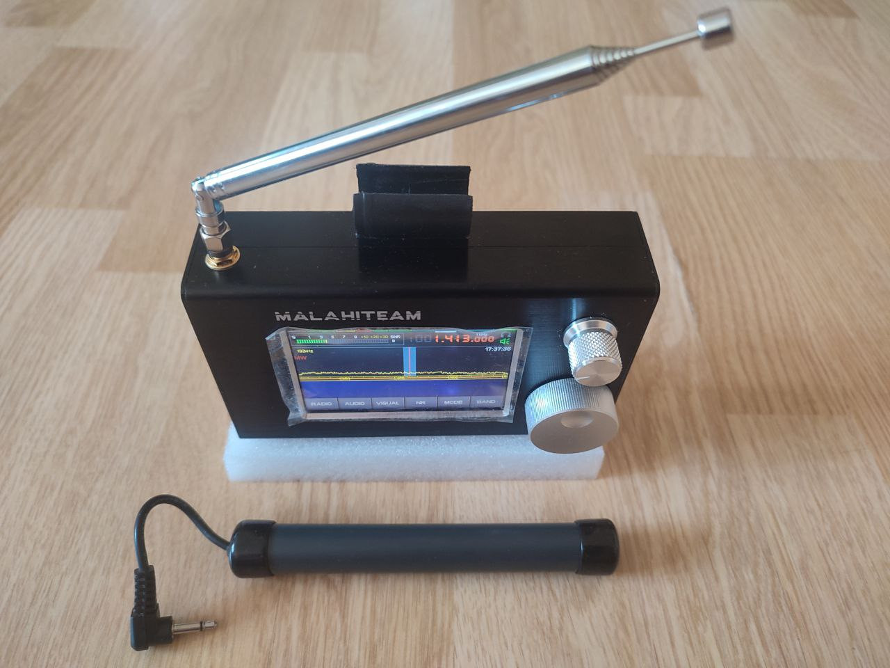
Assembling the Receiver
If you have an assembled receiver, please, skip over this section and
go to the next one. Otherwise, read on.
The receiver is shipped as a kit, without a battery. Hence, you will need
to obtain a single, good, flat-top, unprotected 18650 lithium-ion cell
prior to assembling the receiver. Protected button-top cells will not
fit into the receiver. Manuel Maliszewski has published
a review of available 18650 cells
,
where he suggests using Panasonic / Sanyo NCR18650B or NCR18650GA cells.
18650 cells can be purchased from this online store:
https://www.18650batterystore.com/
Once you obtain an 18650 cell, take a Phillips screwdriver and follow these
instructions to assemble the receiver:
-
Insert the 18650 cell into its holder, found at the rear half of the
receiver. Make sure it is installed in the correct polarity, with the
positive end facing the red wire.
-
Check all wires for cracks, make sure they are firmly connected to the
circuit board.
-
Put two halves of the receiver together, sliding them into the tracks.
Make sure no wires are clamped or otherwise damaged in the process.
-
Holding receiver halves together, attach left and right covers, securing
them with a screwdriver. Make sure that the LED, headphone connector, power
button, and USB connector match holes found in the right-side cover.
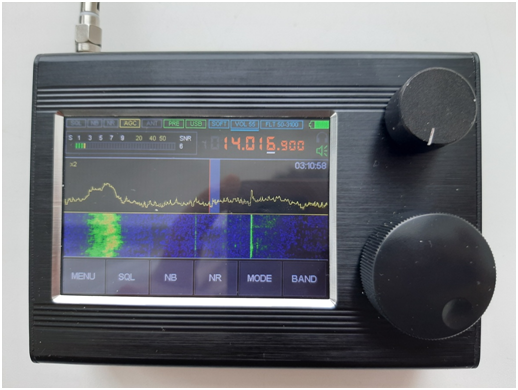
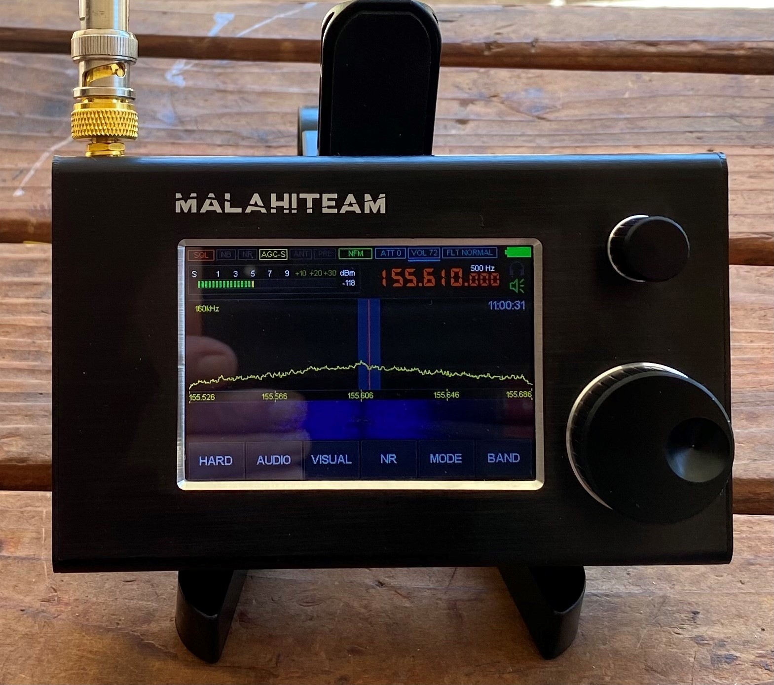
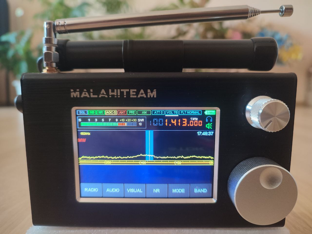
Getting Started
Once you have your receiver assembled, attach and extend the included
telescopic antenna, then click the power button found at the right side
of its case. You should briefly see the title screen, followed by the
main user interface screen:
From top to the bottom, this screen contains the following components:
- Various indicators, discussed further in this document.
- Signal strength meter (S-meter).
- Currently tuned frequency and tuning step.
- Headphone and speaker indicators.
- Panorama display showing signal strength by frequency. The vertical line at the middle is your currently tuned frequency.
- Waterfall display showing how signal changed over time.
- Menu buttons, discussed further in this document.
The basic operation is very simple:
To change the frequency...
Touch the frequency display then use the touch screen to enter a new frequency.
To tune the frequency...
Rotate the larger knob found at the front of the receiver.
To change the tuning step...
Click on the larger knob, rotate it to change the step then click it again.
To change the volume...
Rotate the smaller knob found at the front of the receiver.
To change between volume, filter width, and attenuator...
Click the smaller knob, rotate it to select what you want to change, then
click it again.
To change panorama width...
Touch the lower half of the panorama display. The current width
is indicated at the top-left corner of the panorama.
To change modulation type...
Touch the MODE button, then use the touch
screen to select a new modulation type, such as AM, WFM, NFM, LSB, or
USB.
To quickly turn the screen off...
Click the power button. Clicking it again will turn the screen back on.
To turn the receiver off...
Press and hold the power button for a few seconds. The receiver will issue a
series of Morse code beeps (guess what they mean) and then turn itself off.
Two more functions are toggled with the knobs found at the front of the
receiver:
To disable touch screen...
Press and hold the smaller knob for a few seconds. Disabling touch screen
will reduce the shortwave interference. You will still be able to tune the
receiver by using knobs. Press the smaller knob again to reenable the touch
screen.
To lock the currently tuned frequency...
Press and hold the larger knob for a few seconds. Press the larger knob again
to unlock frequency tuning.
Finally, to set the clock shown at the top-right corner...
-
Hold the RADIO button until the receiver
beeps, showing the time setup screen.
-
Rotate the smaller knob to change values.
-
Click the smaller knob to advance to the next element.
-
Once the date and time are entered, press and hold the smaller knob to
confirm changes.
Exploring the Indicators and Menus
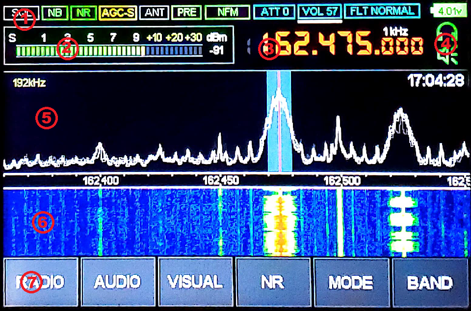
The top of the main screen contains a row of indicators, grayed if disabled,
as follows:
| SQL |
The green light indicates that the squelch has been triggered. The red
light indicates that the squelch is enabled, but not triggered.
|
| NB |
Indicates that the noise blanker is enabled. |
| NR |
Indicates that the noise reduction is on. |
| AGC-S |
Shows current automatic gain control status. |
| ANT |
The green light indicates that the Hi-Z antenna is enabled. The red light
indicates that the antenna power ("bias tee") is enabled (DSP2 only).
|
| PRE |
Indicates that the pre-amplifier is on. |
| NFM |
Shows current modulation type, such as AM, WFM, NFM, LSB, or USB. |
| ATT 0 |
Shows current attenuator setting, in decibels (DSP2 or DSP1 with optional
board only).
|
| VOL 57 |
Shows current volume setting. |
| FLT WIDE |
Shows width of the audio filter applied to the decoded signal. |
| 4.01v |
Shows current battery voltage and status. |
The bottom of the main screen contains a row of menu buttons, as follows:
| RADIO |
Configures the radio-frequency hardware and processing. |
| AUDIO |
Configures the audio hardware and processing. |
| VISUAL |
Configures the panorama and waterfall displays, as well as other visual features. |
| NR |
Toggles the noise reduction feature on and off. |
| MODE |
Switches between different modulation types. |
| BAND |
Lets you save and restore saved frequencies and other settings. |
In the following sections, we will go over each of the above menus in
greater detail.
The Radio Menu
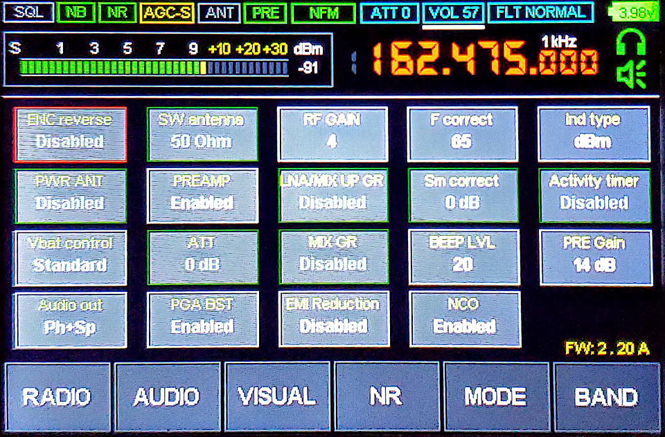
The RADIO menu lets you configure various
hardware features, such as radio frequency gain, pre-amplifier, attenuator,
and so on. Touch a menu item to select it. If an item has more than two
different values, rotate the larger knob to change between these values.
To exit the menu, touch the RADIO button again.
This menu contains the following items.
| ENC reverse |
This item allows reversing the direction of one or both encoder knobs.
|
| PWR ANT |
The receiver has "bias tee" functionality for powering up external
low-noise amplifiers (LNAs) and active antennas. When you enable this
item, the battery voltage will be applied to the antenna connector.
The ANT indicator at the top of the
screen will go red while this feature is on. Keep in mind that the
voltage is going to be in the 3.3V to 4V range and choose your LNA
accoridngly.
|
| Vbat control |
This option does not currently work and will be removed in the future
firmware versions. The receiver will always turn itself off once the
battery voltage falls below the usable limit.
Normally, the receiver will turn itself off once the battery voltage
falls below 3.3V. This item disables the safe voltage threshold and
allows the receiver to operate until the battery is completely depleted.
|
| Audio out |
The audio output can be directed to the built-in speaker, the headphone
jack, or both by using this item.
|
| SW antenna |
Normally, the antenna input has the impedance of 50Ohm, compatible with
most regular, short antennas. This item will enable the high-impedance
(Hi-Z) input mode for better shortwave reception when using telescopic
antennas or a long wire. The ANT indicator at
the top of the screen will go green while this feature is on. The Hi-Z
mode gets automatically disabled at higher frequencies, where it makes
no sense.
|
| PREAMP |
This item toggles the built-in input signal pre-amplifier. Use the
pre-amplifier to receive farther, weaker signals, but keep in mind that
it will also amplify the noise. The PRE
indicator at the top of the screen will go green while this feature is on.
|
| ATT |
High frequency input attenuator value in decibels. This is the same value
as displayed at the top-right corner of the screen. It can also be changed
with the smaller knob. Use attenuation if you are in the vicinity of very
strong stations overloading the receiver.
|
| PGA BST |
Disable this function if you are listening to a very strong signal
overloading the receiver.
|
| RF GAIN |
Signal gain at the wide-band quadrature mixer that is part of the MSI001
chip. Increase this value to amplify input signals. Decrease this value if
you are experiencing too much noise or signal distortions.
|
| LNA/MIX UP GR |
This is an internal MSI001 parameter that can be used to attenuate strong
signals. It behaves differently depending on the tuned frequency:
At 30MHz+ frequencies, where the MSI001 chip uses a built-in
amplifier connected to a single mixer, this item will reduce the
amplifier gain.
At lower frequencies, where the MSI001 chip uses two mixers,
this item will reduce gain at the first mixer input.
|
| MIX GR |
This is an internal MSI001 parameter that can be used to attenuate strong
signals. It behaves differently depending on the tuned frequency:
At 30MHz+ frequencies, where the MSI001 chip uses a built-in
amplifier connected to a single mixer, this item will reduce gain
at the mixer input.
At lower frequencies, where the MSI001 chip uses two mixers,
this item will reduce gain at the second mixer input.
|
| EMI Reduction |
When enabled, this item will reduce the display updates frequency to
reduce interference with the received signal. Enable it if you are
seeing a lot of spurious "spikes" in the panorama.
Please note that the touch screen becomes less responsive when this
item is enabled. Instead of pressing hard on the screen, simply hold
your finger on the same spot for a little longer.
|
| F correct |
This value allows correcting the frequency display shown at the top of
the screen, if it differs from the actual frequency. Simply tune to a
known frequency (the higher the better), then adjust the
F correct value until the displayed
frequency becomes correct.
|
| Sm correct |
This value allows correcting the signal strength meter shown at the top of
the screen, if it differs from the actual strength. Simply tune to a signal
with known strength, then adjust the
Sm correct value until the displayed
signal strength becomes correct.
|
| BEEP LVL |
This item controls the system beep volume. That is the beep you hear when
turning the receiver off, for example. Set it lower if those beeps are too
loud for you.
|
| NCO |
The "numerically controlled oscillator" (NCO) mode, enabled by
this item, allows sampling any signal within current panorama. Normally,
the entire panorama will move as you tune frequency with the larger knob.
In the NCO mode, the tuned frequency within panorama will move until you
reach an edge of the panorama. This mode is also useful for tuning out
internal interference (EMI) by adjusting the panorama frequency separately
from the signal.
|
| Ind type |
This item toggles the signal strength meter, shown at the top of the screen,
between S-levels and decibels (dBm).
|
| Activity timer |
The receiver will turn itself off if you do not touch it for this
preset amount of time in minutes.
|
| PRE Gain |
With the pre-amplifier enabled, this value (in decibels) will be subtracted
from the signal strength meter shown at the top of the screen. This is done
to correct S-meter readings for the pre-amplified signal.
|
The Audio Menu
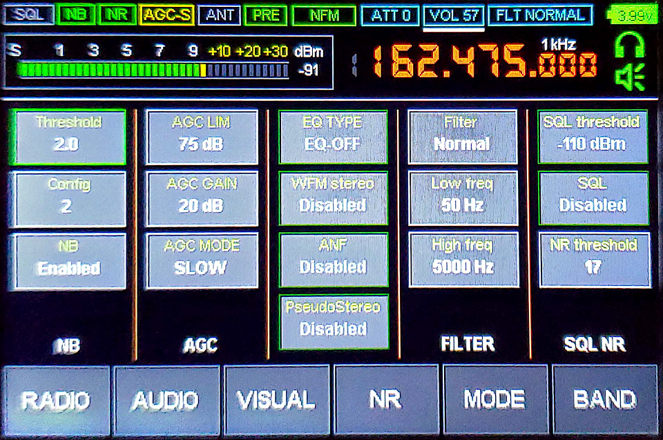
The AUDIO menu lets you configure various
sound characteristics, such as filtering, gain, noise reduction, noise
blanking, and squelch. Touch a menu item to select it. If an item has more
than two different values, rotate the larger knob to change between these
values. To exit the menu, touch the AUDIO button
again. This menu contains the following sections.
Noise Blanking (NB)
The noise blanking feature is used for cancelling the incoming audio noise.
You can enable or disable this feature by clicking the
NB button. The
Threshold value sets the triggering level. It
is not recommended to set it below 3. The
Config option switches between several
different noise blanking configurations. Both parameters depend on the
type of a noise you are trying to blank and thus need to be adjusted
by ear.
Automatic Gain Control (AGC)
The automatic gain control feature is used for automatically adjusting
audio amplification gain. You can choose between three different AGC
modes with the AGC MODE option. The
AGC GAIN value controls how much amplification
is applied. The AGC LIM value sets cut-off
limit for automatic gain control.
Filtering (FILTER)
The Filter option offers three different audio
filter widths: normal, wide, and narrow. This is the same value as displayed
at the top-right corner of the screen. It can also be changed with the
smaller knob. The additional
Low freq and High freq
values set hard thresholds on what sound frequencies can pass through.
Squelch (SQL)
The squelch feature, when enabled with the SQL
button, will completely cut off sound if its level is below a certain
threshold, specified via the SQL threshold
value. The red SQL light at the top of the
screen indicates that the squelch is enabled, but "closed". Once the
sound level exceeds the threshold, the squelch "opens" and the
SQL light goes green.
Noise Reduction (NR)
The NR threshold value specifies the sound
level at which the noise reduction is applied.
Automatic Notch Filter (ANF)
The automatic notch filter allows to suppress carrier tone when using
LSB or USB modulation. This ANF is disabled for other modulation types.
To toggle the filter, click the ANF button.
Broadcast FM Settings
Two of the remaining items have to do with the FM broadcast reception.
The EQ TYPE option selects the equalizer type
applied to the FM radio. The WFM stereo option
toggles FM stereo sound. Please note that you have to enable FM stereo
if you would like to see textual RDS information transmitted by FM radio
broadcasters or automatically scan FM band for stations.
Stereo Effects Simulation
Finally, the PseudoStereo button enables
stereo simulation from mono sound. For obvious reasons, it is only useful
when listening via headphones. The pseudo stereo mode is disabled when
listening to FM broadcast stations using WFM modulation.
The Visual Menu
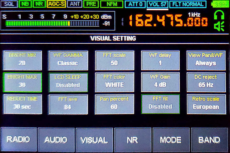
The VISUAL menu lets you configure panorama and
waterfall displays, changing their sensitivity, color scheme, and other
settings. Touch a menu item to select it. If an item has more than two
different values, rotate the larger knob to change between these values.
To exit the menu, touch the VISUAL button again.
This menu contains the following items.
Screen Settings
The regular screen brightness is controlled by the
BRIGHT MAX value. If the screen is left alone
for REDUCT TIME seconds, it will reduce
brightness to the BRIGHT MIN value. If you
enable the LCD SLEEP option, the screen will
turn off after the receiver is left alone for selected number of seconds.
The receiver will continue operating though, with the screen going back on
once you touch it, or any of the knobs.
Waterfall Settings
The WF GAMMA option allows to choose between
several different color schemes for the waterfall. The
WF Gain value can make waterfall more
sensitive to weaker signals, at the cost of showing more noise. Finally,
the WF delay value controls the waterfall
speed.
Panorama Settings
The FFT color option allows to choose the
panorama color. The FFT scale value determines
panorama sensitivity. Finally, the FFT fill
option toggles between plain and filled panorama styles.
The screen percentage taken by the panorama, relative to the waterfall,
is controlled by the Pan percent value.
Disabling Waterfall and Panorama
To reduce interference from the screen, you may want to disable both
waterfall and panorama displays by changing the
View Pan&WF option. With both waterfall
and panorama disabled, the screen will only update when you change the
frequency or other settings. This also applies to the S-meter.
DC Rejection
For proper operation, the receiver supresses the direct current (DC)
signal component that occurs at the 0Hz offset within panorama. While
the DC component does not affect signal reception, it may show up as a
spike at the dead center of the panorama. The
DC reject value controls the supression
strength. Setting it too high may create a "gap" at the panorama center
though.
FM Scale Selection
The receiver includes a separate "retro scale" view of the FM broadcast
band, similar to the old shortwave receiver front panels. While the retro
scale feature will be discussed later in this document, the FM band layout
changes from country to country. The
Retro scale option allows to choose between
European and Japanese FM band layouts.
The Mode Menu
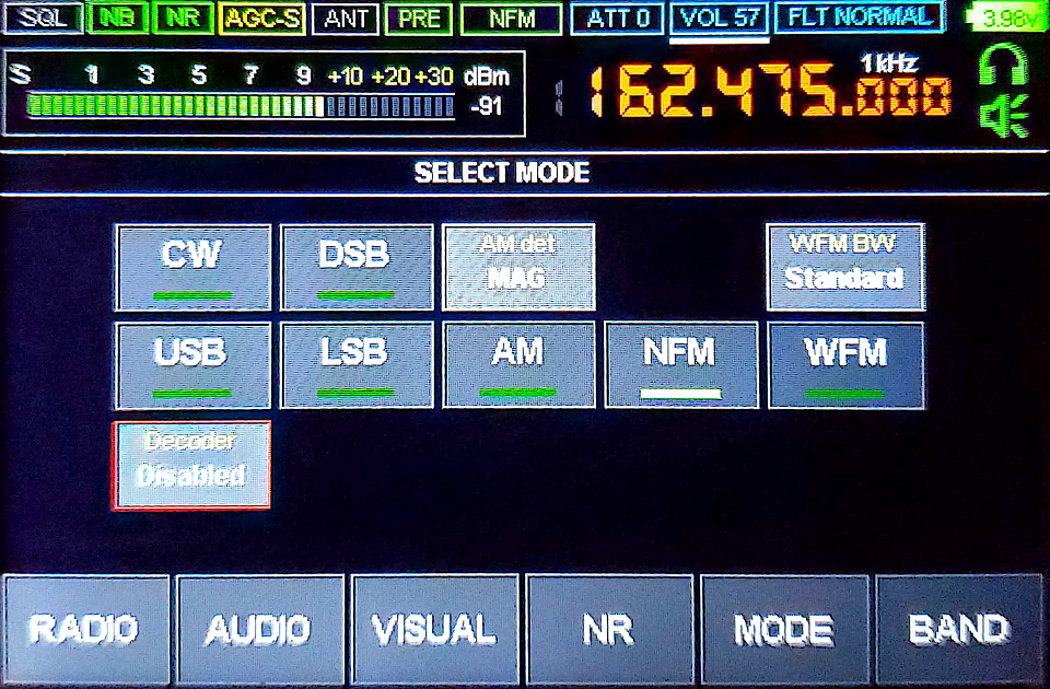
The MODE menu lets you change current modulation
mode (displayed at the top of the screen), as well as enable the CW decoder
feature. Touch a menu item to select it. If an item has more than two
different values, rotate the larger knob to change between these values.
To exit the menu, touch the MODE button again.
This menu contains the following items:
| WFM |
Wide-Band Frequency Modulation
Wide-band frequency modulation used by commercial stations broadcasting in
the FM band. When using WFM modulation, the
WFM BW option selects between normal and narrow
modulation widths. Use the narrow WFM modulation if you are experiencing
interference from adjacent FM broadcasters.
|
| NFM |
Narrow-Band Frequency Modulation
Narrow-band frequency modulation commonly used by police and first responder
radios. Amateur radio operators also use this mode when working in VHF and
UHF bands.
|
| AM |
Amplitude Modulation
Amplitude modulation used by commercial stations broadcasting in LW, MW,
and SW bands, as well as mariners, pilots, and air traffic control. When
using AM modulation, the AM det option selects
the AM demodulator type:
- Classic Amplitude Detector (MAG)
- Synchronous Amplitude Detector (SAM)
- Upper Sideband Synchronous Amplitude Detector (SAMU)
- Lower Sideband Synchronous Amplitude Detector (SAML)
While MAG is the safe default choice, you may want to change to a different
demodulator if the AM signal is too weak or crowded by nearby signals.
|
| LSB |
Lower-Sideband Amplitude Modulation
Lower-sideband amplitude modulation commonly used by amateur radio operators
working in 160M, 80M, and 40M bands.
|
| USB |
Upper-Sideband Amplitude Modulation
Upper-sideband amplitude modulation commonly used by amateur radio operators
working in 20M and higher frequency bands.
|
| DSB |
Dual-Sideband Amplitude Modulation
This option, when combined with LSB or
USB, will automatically choose the sideband that
has higher signal level.
|
| CW |
CW Mode
This option, when combined with LSB or
USB, shrinks the audio filter to the 1kHz
width, useful for listening and decoding Morse code (CW) transmissions.
The LSB / USB
indicator at the top of the screen will change to
CWL / CWU
respectively.
This option is not compatible with the noise reduction (NR) feature!
|
| Decoder |
CW Decoder
When enabled, the CW decoder feature will attempt to decode Morse code
(CW) transmissions and show them below the panorama display. Adjust the
Min SNR value to around 29 for the best
decoding performance. To further improve CW decoding, you may want to
enable the CW option and disable the noise
reduction (NR).
|
The Band Menu
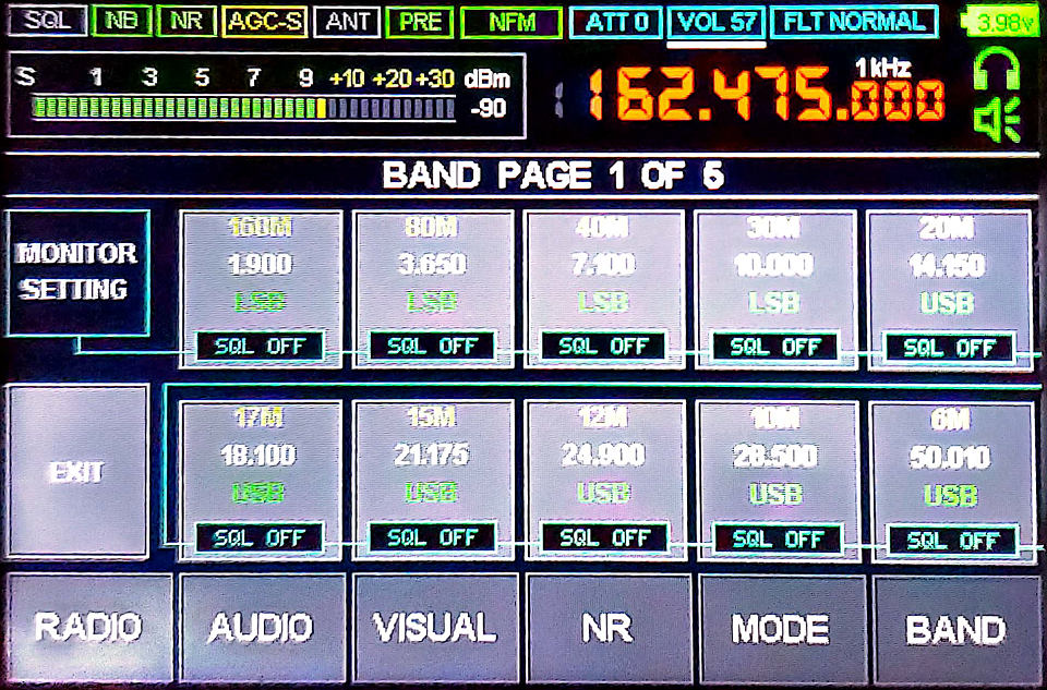
The BAND menu allows to save and restore current
receiver settings to a collection of memory slots. These slots are organized
into pages, flipped by rotating the larger knob. To exit the menu, touch the
BAND button again, or touch the
EXIT button.
To save current settings to a memory slot...
Touch and hold chosen slot for a couple of seconds, until you hear a beep.
You will then be offered opportunity to name saved slot.
To restore settings from a memory slot...
Briefly touch chosen slot.
Monitoring Memory Slots
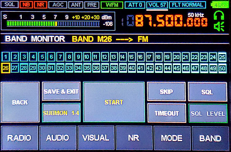
The band monitoring mode is entered by touching the
MONITOR SETTING button in the
BAND menu. It lets you monitor selected
memory slots for activity.
Once in the band monitoring mode, you can quickly browse through memory
slots by rotating the larger knob. All monitored slots are marked in
BLUE. A slot can be skipped from monitoring
by touching the SKIP button. All skipped slots
are marked in GRAY.
After you touch the START button, the receiver
will automatically scan through monitored slots until the
STOP button is pressed. The number of seconds
the receiver stays at each slot is selected by touching the
TIMEOUT button.
Each memory slot has associated optional squelch level. If the
signal level is below that squelch level, the monitor will automatically
skip to the next slot. The squelch option can be toggled by selecting a
slot with the larger knob and touching the
SQL button. Once the squelch is enabled, its
level can be adjusted by touching the
SQL LEVEL button.
To exit back into the BAND menu, touch the
BACK button. To exit all menus at once, touch
the SAVE & EXIT button.
Monitoring Groups of Memory Slots
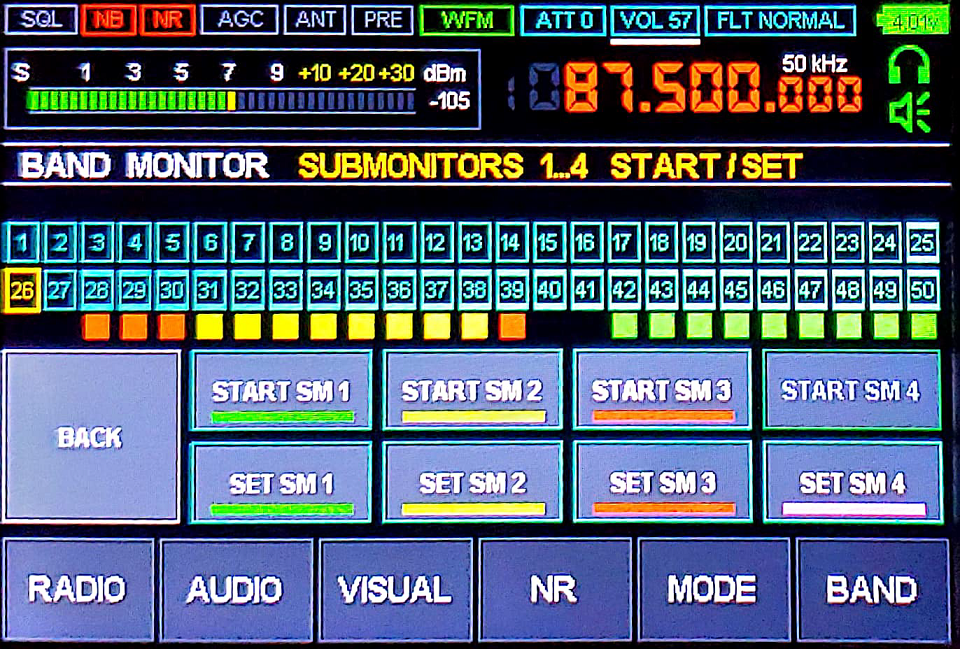
The receiver offers four groups of memory slots that can be monitored
separately from each other and the main monitor. These groups, called
"submonitors", are accessed by touching the
SUBMON 1-4 button at the main monitoring
screen.
The submonitor screen has four START SMx
buttons that start scanning corresponding submonitors. There are also
four SET SMx buttons for editing each
submonitor. Once you touch a SET SMx button,
select memory slots with the larger knob, then touch the
SET/RESET button to include or exclude
them from a submonitor. The BACK button
will always take you to a previous screen.
The FM Retro Scale
When using WFM modulation, the receiver offers the "retro scale" view,
similar to the front panels found in the old shortwave receivers.
To enter the retro scale view...
-
Tune receiver to the FM broadcast band (75-109MHz). The active FM bands
depend on the geographical region set with the
Retro scale option in the
VISUAL menu.
-
Select WFM modulation type in the
MODE menu.
-
Click on the waterfall display twice, until the retro scale shows up.
Once in the retro scale view...
-
Use the larger knob to move between stations.
-
Click on the lower half of the scale to go back to the regular
panorama view.
-
Click on the upper half of the scale to enter the retro scale menu.
The retro scale menu, invoked by clicking on the upper half of the scale,
offers options to add, delete, and edit stations. It contains the following
buttons:
| SWITCH USER SCALE |
The receiver offers two separate user-defined scales. This item
lets you switch between these two scales.
|
| CHANGE COLOR |
Select retro scale color by rotating the larger knob or clicking on a
corresponding color sample. Once done, press the
SAVE COLOR & EXIT button to confirm
your choice or CANCEL button to abandon
changes.
|
| LOAD PRESET |
The receiver contains pre-programmed scales for a multitude of cities.
This item lets you select the scale for a city where you live by using the
larger knob. Keep in mind that your current scale will be lost,
getting replaced by the pre-programmed scale.
|
| RENAME SCALE |
Rename your current scale, rotating the larger knob to select letters. Once
you select the next letter, press the larger knob to confirm it and go to
the next letter. You can restart the name entry by clicking the
CLEAR NAME button. Once done, press
SAVE AND EXIT button to confirm, or
CANCEL button to abandon changes.
|
| CLEAR SCALE |
This item lets you completely clear the current user-defined scale,
removing all stations and the custom scale name, if any. Press the
CLEAR button to confirm, or
CANCEL button to keep your current scale.
|
| ADD/EDIT STATION |
Before editing or adding a new station, tune to its frequency with the
larger knob. Enter or change station name by using touch screen or
rotating the larger knob to select letters. Once satisfied with your
input, press SAVE AND CONTINUE to edit the
next station, or SAVE AND EXIT to go back
into the menu. Press DELETE STATION to
completely remove the current station entry. Finally, press
CANCEL to abandon changes.
|
| AUTOSEARCHING |
This auto-search feature makes the receiver scan FM band looking for
stations and automatically populate the current scale with found
stations. It is described in the next section of this document.
|
| CANCEL |
Exit the menu back into the retro scale view.
|
The Auto Search
The retro scale lets you scan the airwaves and populate your scale with
found FM stations. The searched FM bands depend on the country set with
the Retro scale option in the
VISUAL menu. In order to use the
auto-search feature, follow these steps:
-
Go into the RADIO menu and make sure
that the headphone output is enabled in the
Audio out option. The auto-search will
not work with the headphone output disabled.
-
Go into the AUDIO menu and make sure the
WFM stereo option is enabled. The
auto-search will not work with the WFM stereo disabled.
-
Go into the retro scale menu by clicking on the upper half of the scale
and click the AUTOSEARCHING button.
The auto-search screen shows the progress bar, the number of found
stations, and the pilot tone indicator. The auto-search can be cancelled
at any moment by clicking the CANCEL button.
Once the auto-search completes, it presents the choice of saving the
results to your current scale with the
SAVE SCALE & EXIT button or abandoning
them with the CANCEL button. Keep in mind
that the prior contents of the scale will be lost if you choose
to replace them with the auto-search results.
Connecting Receiver to a Computer
The following instructions assume that you are connecting the receiver to
a PC running Microsoft Windows 10 or similar operating system.
Windows 10 is supposed to have all the drivers needed to interface it
with the Malahit receiver and thus does not require any third party
drivers.
You will need a micro USB cable (shipped with most cell phones) to connect
Malahit to a PC. Make sure your micro USB cable supports data
connections. Once you connect the receiver to any available USB port
on your PC and turn the receiver on, you should see the following three
new USB devices in the Windows Device Manager panel:
- Malahit RX
This is the audio input device that brings sound from the receiver into
the computer. You can use it the same way you would use a regular
microphone device.
- Malahit IQ
This device is also treated as an "audio input" of sorts, but it carries
the entire 192kHz of the panorama data. You can use this device with
various SDR software packages (such as
HDSDR,
SDR++, or
SDR#) to
receive and process the same panorama as received by the Malahit.
- Malahit CAT
This is a USB-connected serial port used to tune Malahit's frequency,
select modulation, volume, and other parameters. The command set used
by the receiver is compatible with the Kenwood TS-480 command
set.
Once you have verified that the Malahit USB devices show up in the
Windows Device Manager panel, go into the Windows Sound
Control panel and make sure both "Malahit RX" and
"Malahit IQ" sound inputs are enabled.
Verifying Connection with HDSDR
Now, let us verify the receiver functionality with the popular
HDSDR application for Windows, by following these
steps:
-
Install and run the HDSDR
software.
-
Select "Options | Select Input | Sound Card", since the receiver
acts as a sound card device.
-
Click on "Soundcard" and select "Malahit IQ" in the
"RX input (from Radio)" box.
-
Click "Ok" to confirm your choice.
At this point, the HDSDR should show the same panorama and
waterfall displays as your receiver. Use the receiver controls to
tune the frequency.
Controlling Receiver from a Computer
To tune the receiver frequency from a computer, you will need to interface
the OmniRig software
with the "Malahit CAT" USB device.
-
Go into Windows Device Manager and find what COM-port device your
"Malahit CAT" is associated with. This can be done by disconnecting
and reconnecting the Malahit receiver. One of the COM-port entries
underneath the "COM & LPT" branch should disappear and then
reappear. That will be your COM-port device. It may change if you
reconnect the receiver to a different USB socket.
-
Install and run the
OmniRig.
In the OmniRig window, configure "RIG 1" as follows and
confirm your changes by clicking "Ok".
Rig Type  = TS-480
Port      = <your COM-port>
Baud Rate = 19200
Dara Bits = 8
Parity    = None
Stop Bits = 1
RTS       = High
DTR       = High
Poll      = 500
Timeout   = 4000
- In the HDSDR, select "Options | CAT to Radio | Sync RIG1",
enable "Use v1", "Sync to Rig", "Sync from Rig",
"Sync LO Frequency", and "Sync Modulation" in the same menu.
You should now be able to control Malahit receiver by changing frequency
and other settings in the HDSDR software.
Updating Firmware
The Malahit development team releases firmware updates on the regular
basis, publishing them at their
web site. On Windows,
follow these steps to flash your receiver with the new firmware:
-
Install
STM32CubeProgrammer
software, which we are going to use for flashing.
-
After making sure your Malahit receiver is fully charged, turn off your
receiver.
-
Press both receiver knobs. While holding them down, turn the receiver
on with the power button. Release the knobs. The receiver LED should
start blinking red and green, indicating that the receiver is now in the
DFU mode and ready to accept new firmware.
-
Connect receiver to the computer. At this point, you should see
"MALAHIT RECEIVER DFU" device in the Windows Device Manager.
-
Click the right mouse button on the STM32CubeProgrammer desktop icon
and select "Run as administrator" from the popup menu to run the
program with administrative privileges.
-
In the STM32CubeProgrammer window, find the drop down menu to the
left of the green Connect button and
select "USB" from that menu.
-
Click on the 🔄 icon to the right of the USB port name to refresh
USB configuration, then click on the green
Connect button. Upon successful
connection, the green button should turn into
Disconnect.
-
Click on the "hard drive download" icon at the left edge of the
STM32CubeProgrammer window. This should bring up the "Erasing
& Programming" screen.
-
Click on the Browse button and select the
firmware file you would like to flash. All valid firmware files will
have .BIN extension (as in "M2_FW2_10_F.bin").
-
Check "Verify programming" and "Run after programming"
checkboxes. Leave the rest of checkboxes unchecked.
-
Click on the Start Programming button to
proceed with the flash.
-
The STM32CubeProgrammer window will indicate the flash progress at
its bottom. Once it is done flashing, the program will display the success
message.
-
Once done flashing, click on the Disconnect
button and the receiver should reboot into freshly flashed firmware.
If flashing fails, you can repeat the above process as many times as
necessary. This will not damage your device.
Dealing with Internal Interference
The Malahit receiver is essentially a little computer containing
multiple digital components, such as CPU, display, and the touch screen.
Since all these components operate by using digital signals, they all
generate their own electromagnetic noise affecting reception. In this
section, we will go over common interference sources inside the receiver
and how to deal with them.
Touch Screen Noise
The touch screen noise mostly occurs in shortwave bands and manifests as
a constant buzzing sound that becomes louder when you touch the screen.
The best way to deal with it is by moving your antenna at least several
meters away from the receiver. If this is not possible (when using a
telescopic antenna for example), you can temporarily disable the touch
screen by pressing and holding the smaller knob for a few seconds.
You will still be able to tune the receiver by using knobs. Press and
hold the smaller knob again to reenable the touch screen.
Display Noise
The display noise usually occurs in the VHF and adjacent bands. It
manifests as prominent "bumps" or "spikes" on the panorama display, often
obscuring useful signals. Once again, the best way to deal with it is by
moving your antenna at least several meters away from the receiver. If
this is not possible, reduce the display noise by going into the
RADIO menu and enabling the
EMI Reduction option. This will slow down
display updates, reducing the interference, at the cost of making the
touch screen more sluggish. Finally, you can temporarily disable the
display by clicking the power button. You will still be able to tune
the receiver by using knobs. Press the power button again to reenable
the display.
Choosing the Right Antenna
Your antenna choice will always depend on the frequencies you would like
to receive and the amount of radio interference at your location. In this
section, we will go over some available options.
Telescopic Antennas
The receiver comes with a short telescopic antenna that can be used
at a wide variety of different frequencies, as long as you do not have any
strong electromagnetic interference sources nearby. Possible interference
sources include power supplies, phone chargers, LED lights, refridgerators,
air conditioners, water pumps, and other devices.
The stock telescopic antenna is not the best choice in the LW, MW, and SW
bands (<30MHz), but can still be used there. To improve the reception
in these bands, go to the
RADIO menu and enable the
SW antenna option to go into the
high-impedance (Hi-Z) antenna mode. The
ANT indicator at the top of the screen will go
green while this feature is on. The Hi-Z mode is automatically disabled
at higher frequencies, where it makes no difference. You may also want to
enable the PREAMP option for additional
signal amplification, at the cost of more noise.
Other telescopic antennas can also be used with the receiver. They all
work approximately the same, with longer antennas being more sensitive
at lower frequencies. More expensive telescopic antennas are made of
sturdier materials and offer better articulation. Some popular choices
are
Comet SMA-W100RX2
and
Diamond SRH789.
Some antennas come with BNC connectors and will require a BNC-to-SMA
adapter to attach to the receiver. Whatever telescopic antenna you choose,
keep in mind that heavier antennas put more strain on the SMA connector
and may eventually damage it. You may also want to consider using a cable
in order to keep the antenna away from the receiver. This reduces
both the mechanical stress on the connector and the interference from
receiver's internal circuitry, such as touch screen.
Long Wire Antennas (LW, MW, SW)
The optimal length of a telescopic antenna should be close to 1/2 of the
wavelength you expect to receive. For example, if you are planning to
listen to the 25m shortwave band, the optimal antenna length will be
25 / 2 ~= 12.5 meters
which makes good shortwave telescopic antennas rather difficult to
implement. It is still possible though to attach a really long wire to the
antenna connector, throwing it outside or wrapping it around a room as
necessary. Shortwave radio manufacturers offer such antennas as
Sangean ANT-60,
Tecsun AN-05,
or
XHDATA AN-80,
where the wire conveniently retracts into a reel. Same as telescopic
antennas, long wires are susceptible to the electromagnetic interference.
Rubber Whip Antennas (VHF, UHF)
At shorter wavelengths (80MHz+), it is possible to use short rubber
whip antennas made for the use in walkie talkies, first responder radios,
and scanners. These antennas are small, very portable, and offer decent
reception in the FM, VHF, and UHF bands. Some examples are
Nagoya NA-701,
Nagoya NA-771,
Comet SMA-501,
and
Comet SMA-503.
It is necessary to say though that these antennas are specifically tuned
for the VHF and UHF bands and thus become useless in the LW, MW, and SW
bands.
Loop Antennas
As mentioned in the previous sections, the electromagnetic interference
is often a huge problem when listening to the radio indoors or in urban
environment. The magnetic loop antennas attempt to work around this
interference by receiving the magnetic component of the signal rather
than noisier electric component.
A typical loop antenna consists of one or more relatively small loops
of wire connected to a receiver via a tiny transformer ("balun" or
"unun"). The total surface of the wire loop determines how much magnetic
flux it receives, making bigger loops more sensitive. A loop antenna
is directional, with the maximum gain achieved when a side of the loop
is directed towards the signal source.
While loop antennas are less susceptible to the eletromagnetic
interference, they are also less sensitive than conventional antennas.
Thus, most commercial loop antennas include low-noise amplifiers,
requiring a power source. Some commercially available loop antennas
are
YouLoop,
MLA-30+,
and
GA-450.
Accessories
Malahit receivers have been modified in different ways, to improve their
characteristics or make them more comfortable to use. Additionally, there
are people offering accessories made specifically for these receivers. In
this section, we will go over some of these accessories.
Connecting BNC Antennas
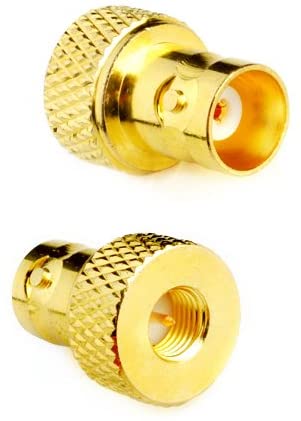 Since the receiver comes with a female SMA connector, it requires an adapter
for connecting BNC accessories. Using a heavy BNC adapter may damage the
stock SMA connector. Fortunately, there are slim BNC adapters
on Amazon,
among other places.
Since the receiver comes with a female SMA connector, it requires an adapter
for connecting BNC accessories. Using a heavy BNC adapter may damage the
stock SMA connector. Fortunately, there are slim BNC adapters
on Amazon,
among other places.
Magnetic USB Cables
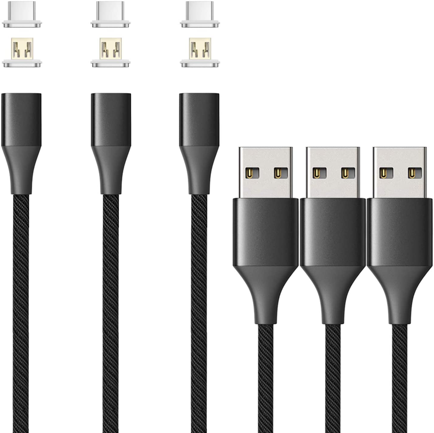 The micro USB socket inside the receiver is soldered directly to the
circuit board and may eventually break off because of the repetitive
stress. To avoid this problem, consider using a magnetic USB cable,
available from many sources at
Amazon
and other ecommerce sites. These products consist of a tiny insert
that plugs into the micro USB socket and a special cable safely
attaching to that insert by magnetic force.
The micro USB socket inside the receiver is soldered directly to the
circuit board and may eventually break off because of the repetitive
stress. To avoid this problem, consider using a magnetic USB cable,
available from many sources at
Amazon
and other ecommerce sites. These products consist of a tiny insert
that plugs into the micro USB socket and a special cable safely
attaching to that insert by magnetic force.
Better Encoder Knobs
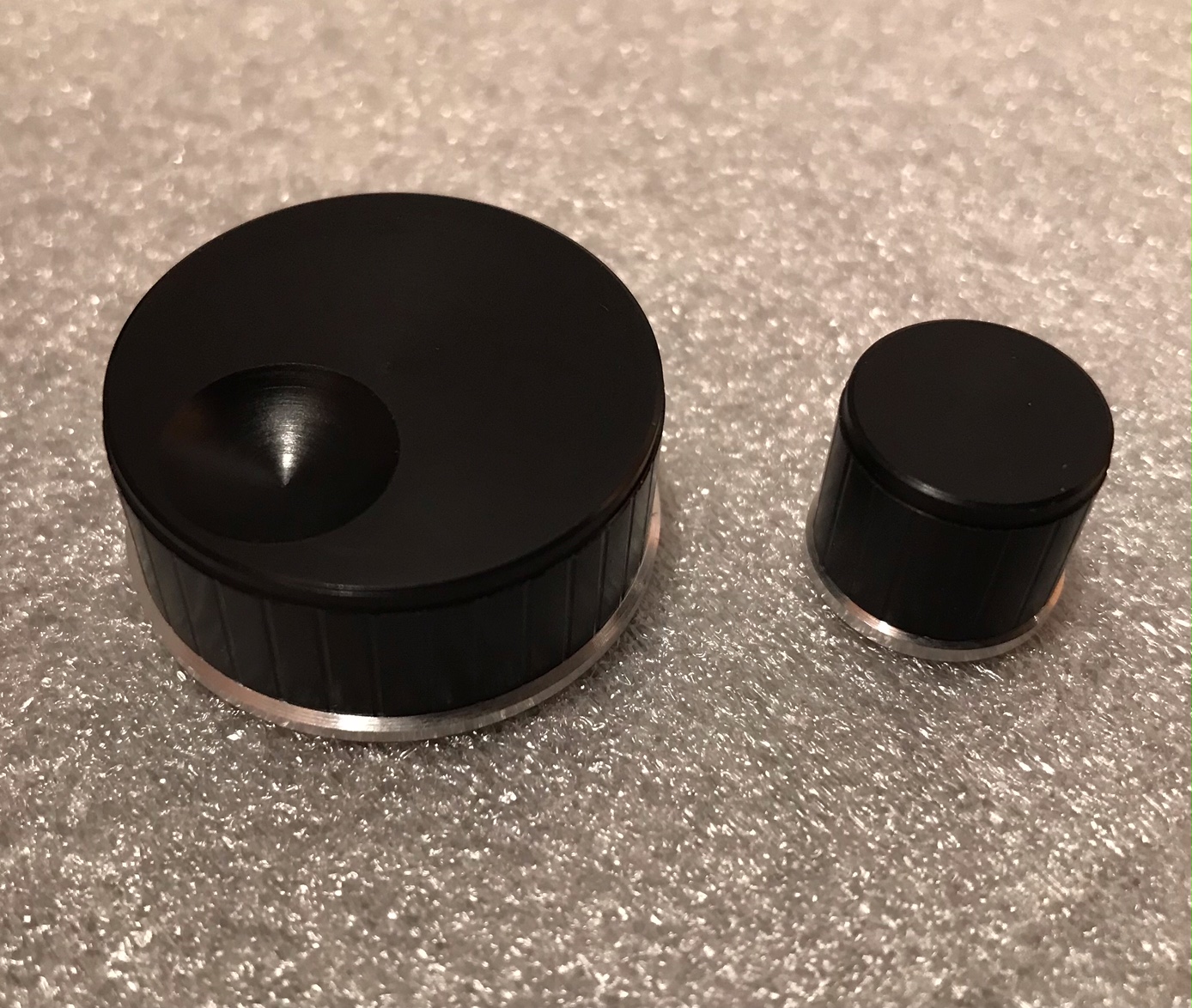 Nikolay
makes better encoder knobs, as shown below. At the time of writing this
text, these knobs cost 14 euros when shipped from Russia to the EU, 17
euros when shipped to the US. You can contact Nikolay by
emailing
him in English or Russian. Similar, but less impressive knobs can be
obtained from
Amazon
and other online shops.
Nikolay
makes better encoder knobs, as shown below. At the time of writing this
text, these knobs cost 14 euros when shipped from Russia to the EU, 17
euros when shipped to the US. You can contact Nikolay by
emailing
him in English or Russian. Similar, but less impressive knobs can be
obtained from
Amazon
and other online shops.
Custom Stands
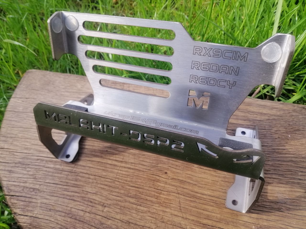
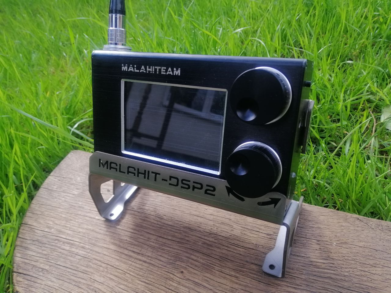 Serhii produces custom Malahit
receiver stands made of stainless steel, as shown below. At the time of
writing this text, these stands cost 40 euros when shipped from Ukraine
to the EU, 44 euros when shipped to the US. You can contact Serhii by
emailing
him in English or Russian.
Serhii produces custom Malahit
receiver stands made of stainless steel, as shown below. At the time of
writing this text, these stands cost 40 euros when shipped from Ukraine
to the EU, 44 euros when shipped to the US. You can contact Serhii by
emailing
him in English or Russian.
Bluetooth Transmitters
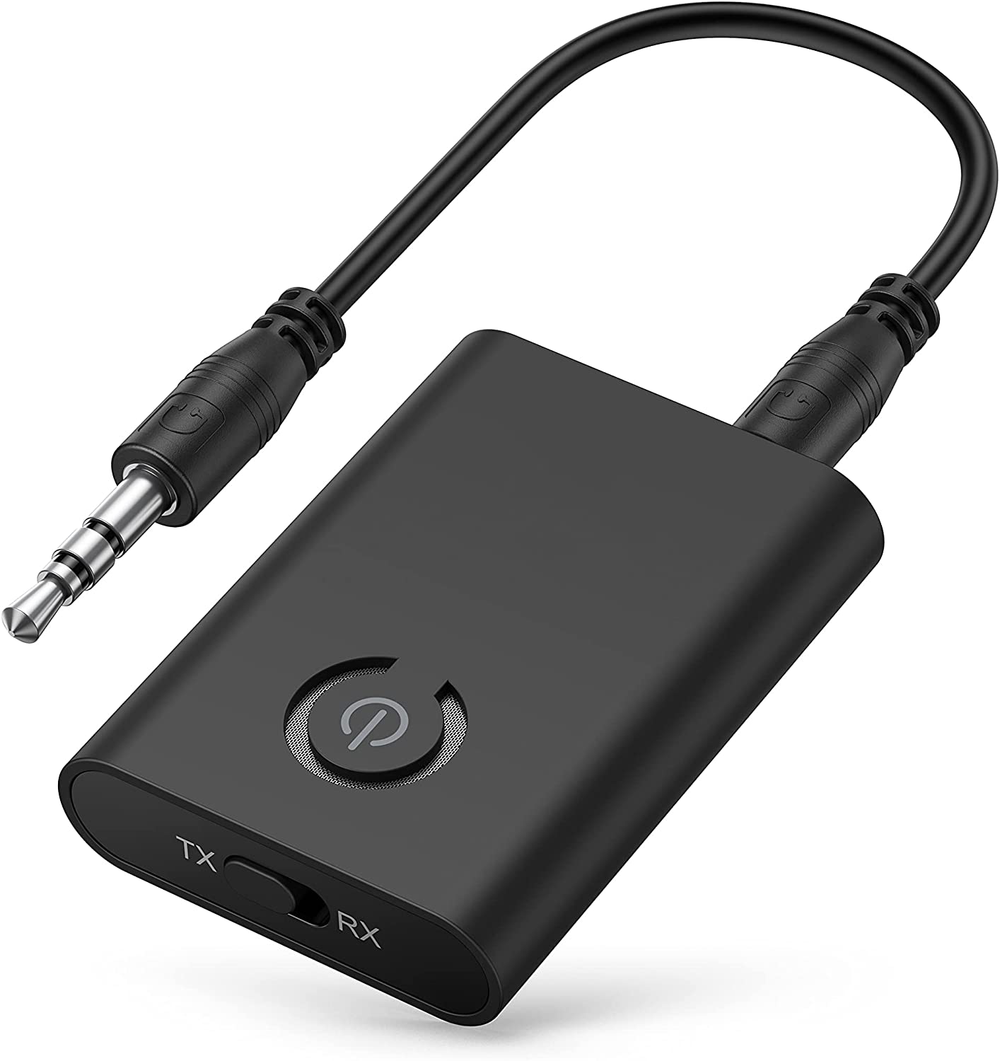 While the receiver does not have built-in Bluetooth interface for
connecting wireless headphones, an external Bluetooth transmitter
can be purchased
on Amazon,
among other places, and plugged into Malahit's audio output. For
convenience, attach it to the back of the receiver with a piece of
Velcro.
While the receiver does not have built-in Bluetooth interface for
connecting wireless headphones, an external Bluetooth transmitter
can be purchased
on Amazon,
among other places, and plugged into Malahit's audio output. For
convenience, attach it to the back of the receiver with a piece of
Velcro.
Ferrite Antennas
 Vladislav (R6FDF) makes active
ferrite antennas for superior reception in LW, MW, and lower SW bands.
The ferrite antenna works much better than the stock telescopic antenna
at these bands, especially when used inside buildings and other noisy
environments. The antenna attaches to the top of the receiver and plugs
into the SMA socket. Malahit-DSP2 receivers will power the antenna
using the bias tee. You can contact Vladislav by
emailing
him in English or Russian.
Vladislav (R6FDF) makes active
ferrite antennas for superior reception in LW, MW, and lower SW bands.
The ferrite antenna works much better than the stock telescopic antenna
at these bands, especially when used inside buildings and other noisy
environments. The antenna attaches to the top of the receiver and plugs
into the SMA socket. Malahit-DSP2 receivers will power the antenna
using the bias tee. You can contact Vladislav by
emailing
him in English or Russian.
SV2CZF Antennas
 Theo (SV2CZF) designs and builds a variety of
small, highly effective antennas,
including MWA30, TWA30P, and SAR32M. These antennas have proven to work
very well with the Malahit receiver, as seen in the
SAR32M review by Manuel Maliszewski.
You can contact Theo by emailing him
in English. Theo also has a
Facebook group
where he posts news about his products.
Theo (SV2CZF) designs and builds a variety of
small, highly effective antennas,
including MWA30, TWA30P, and SAR32M. These antennas have proven to work
very well with the Malahit receiver, as seen in the
SAR32M review by Manuel Maliszewski.
You can contact Theo by emailing him
in English. Theo also has a
Facebook group
where he posts news about his products.
Modifications and Repairs
This section will cover Malahit receiver modifications and repairs.
Changing DIP Switches
Inside the receiver case, there is a block of DIP switches. These
switches control experimental firmware features that have not yet
made it into the on-screen user interface:
- DIP2 -- Safe Power-On Sequence
With this switch enabled, the receiver will only turn on after
you click the power button three times. This is done to
prevent random power-ons when something accidentally touches
the power button.
- DIP3 -- Higher Display Frequency in WFM Mode
When this switch is on, and the receiver is in the WFM mode, it
will run the display at higher frequency. Lower display frequency
will be used when this switch is off.
- Other Switches
Please, do not touch any other DIP switches, as this may
interfere with the normal operation of the receiver.
Using Two 18650 Cells
To extend operating time, you can put two 18650 lithium cells into your
receiver. Some receivers even come with a battery holder fitting two cells.
If your receiver has a single battery holder, you will have to replace it
with a dual type. Since the receiver expects single cell voltage, your
battery holder should connect cells in parallel. Do not connect
cells in series, since it will damage your receiver.
It has also been reported by multiple Malahit users that the cells may
touch and short encoder pins inside the case. While this does not
cause spontaneous combustion, the encoders may stop working as result.
Make sure your cells do not touch encoder pins and bend pins
away if it happens.
To avoid power drain and excessive heat...
-
Always use the same exact cells, same model, from the same
manufacturer, preferably from the same batch.
-
Before placing cells into the receiver, make sure to fully charge both
cells, with external charger if necessary.
Manuel Maliszewski provides more information on
connecting and managing two 18650 cells
in his blog. He is also suggesting
the best 18650 cells
to use.
Replacing SMA Connector
The SMA connector or the cable connecting it to the receiver board may
break after a lot of use. If this happens, the replacement part is
as follows:
| 150mm SMA-to-MCRF Cable |
|
100mm SMA-to-MCRF Cable |
MOLEX 0897629524 |
|
MOLEX 0897613412 |
Fixing and Replacing Encoders
If an encoder starts skipping or even going backwards when rotated,
consider putting a few drops of alcohol into it, to clean the encoder.
Remember that by cleaning encoder with alcohol, you also remove
some of the grease that prevents surface oxidation inside the
encoder. Hence, once the alcohol evaporates, put some silicon oil in.
The oil will protect contact surfaces from oxidation on contact with
the air.
CAIG produces a line of DeoxIT
products for cleaning and libricating mechanical encoders and switches.
DeoxIT F5
can be used for flushing and lubrication, while
DeoxIT D5
will also remove oxidation and corrosion. Finally, for adding tactile
feel, apply
DeoxIT FaderGrease
after using either of the cleaning products.
If one or both of the encoders stop working, open the receiver and check
if their leads are touching any of the 18650 cells. While not dangerous
to the cells, this will effectively short encoder leads, preventing
encoder from working. If this happens, insulate the leads or simply bend
them away a little.
The mechanical encoders used in the receiver are known to wear our and
break over time. If any of your encoders break, the replacement parts
are as follows:
| Frequency Encoder |
|
Volume Encoder |
BOURNS PEC11R-4020K-S024 |
|
BOURNS PEC11R-4220K-S024 |
The only difference between these two parts is that the volume encoder
will click when rotated.
Useful Resources
This section contains links to documentation, software tools, and
general reference databases.
Other Documentation
General Software
- OmniRig CAT Control
You will need this software in order to control Malahit from a Windows
computer.
- Virtual Audio Cable
This software creates a virtual "audio cable" for connecting SDR receiver
apps to digital decoder apps on Windows.
- HDSDR
SDR receiver for Windows that supports any SDR hardware implementing
ExtIO DLL API. It also works with wideband audio sources, such as
Malahit.
- SDRSharp (aka SDR#)
SDR receiver from AirSpy. This application is written in C# and runs on
Windows. It is made to support AirSpy's own SDR products, but will
happily work with Malahit. When connecting Malahit to SDR#, make sure you
identify it as a "FUNcube Dongle Pro+" device to access the whole
192kHz spectrum.
- SDR++
Simple, open source, cross platform SDR receiver that runs on Linux,
Windows, and Android.
- CubicSDR
Open source SDR receiver that primarily runs on MacOS, but also
supports Linux and Windows.
Digital Radio Software
General Reference
- Tuning from 0 to 30MHz
The detailed explanation of frequencies and signals found at the lower side
of the spectrum, in LW, MW, and SW bands.
- QRZ HAM Callsign Database
Address book of HAM operators around the world, searchable by call sign.
- QRZCQ HAM Callsign Database
Another address book of HAM operators, searchable by callsign.
- Shortwave Radio Frequency Schedule
Index of shortwave broadcasters, with frequencies, times, and locations.
Search by station name, frequency, band, or time.
- Shortwave Schedule
Another searchable index of shortwave broadcasters. Search by station name,
frequency, or see currently transmitting stations.
- Radio Locator
Searchable index of AM and FM stations closest to your location. Only
works for US locations though.
- Signal Identification Guide
Visual guide to radio signals, for identifying modulation types and signal
sources.
- RadioReference
Forums, frequency database, trunked radio information, and FCC license data.
Compiled and maintained by Marat Fayzullin
Translated to Russian by Victor Shulzhenko
Proofread by Sergey Belikov